



A part can pass every dimension and still fail the drawing
Linear dimensions tell you a hole is the right diameter and sits roughly where it should. They don’t tell you whether that hole’s position holds within its true positional tolerance relative to the datum structure the designer actually specified, and a part can hit every individual dimension on the print while still failing that positional callout badly enough to reject the assembly. GD&T exists precisely because features don’t function in isolation, a bolt pattern has to align with a mating part, a bore has to stay concentric with a shaft, and none of that gets verified by measuring each feature on its own without reference to the others.
Why datum structure decides the whole inspection
Every GD&T inspection starts with establishing the datum reference frame exactly as called out on the drawing, primary, secondary, and tertiary datums locked down in the correct order before a single tolerance gets checked against them. Get the datum sequence wrong and every downstream measurement is wrong too, even if the raw coordinate data collected off the part was perfectly accurate. This is where a lot of in-house inspection goes sideways, someone measures a feature correctly but references it against the wrong datum plane, and the report comes back showing a failure that isn’t real, or worse, a pass that should have failed.
Complex parts with datum features that shift under different fixturing methods make this harder still. A thin-walled part can measure differently depending on how it’s clamped, and a datum surface that isn’t rigid enough to hold its position under normal fixturing pressure introduces variation into the measurement before the actual part geometry even enters the picture.

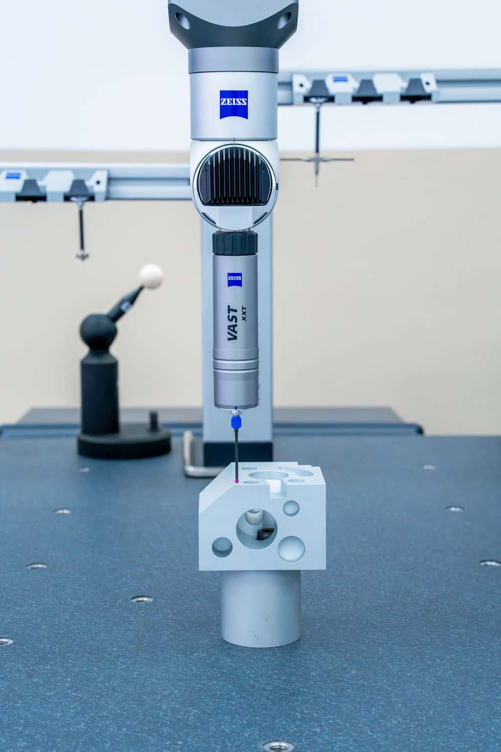
What a CMM actually checks, and how
Position tolerance verification confirms a feature’s location falls within its allowed tolerance zone around true position, calculated from the datum structure rather than from a simple linear offset. Profile tolerance, whether of a surface or a line, checks a boundary condition around the entire feature rather than a single point measurement, which matters on curved or contoured features where a single-point check would miss deviation sitting just outside the sampled locations. Flatness, perpendicularity, and parallelism round out the geometric checks most commonly called out on machined parts, each one verifying a relationship rather than a standalone dimension.
Runout and concentricity checks come up constantly on rotating parts, shafts, hubs, anything that has to spin true relative to a datum axis without excessive wobble under load. A part that measures the correct diameter everywhere along its length can still fail a runout check if that diameter isn’t centred consistently on the rotational axis, and that failure mode only shows up when the inspection is actually built around the GD&T callout rather than a basic diameter check.
Where the deviation actually comes from
A part doesn’t drift out of GD&T tolerance for no reason. Deformation during machining or moulding pulls a feature away from its nominal position as internal stress releases unevenly. A worn tool changes the geometry it’s cutting or forming slightly with every cycle, so a positional tolerance that held fine on part one can drift by part five hundred without anyone changing the programme. Vibration on the machine itself introduces a different kind of error again, one that shows up as inconsistent form rather than a steady drift in one direction, and temperature swings across a shift do the same thing to material that hasn’t fully stabilised before it’s measured. Knowing which of these is actually driving a failed characteristic matters more than just reporting the failure, because a tool wear problem gets fixed differently to a fixturing or thermal one.

The software doing the actual calculation
Full-field measurement data, whether from a CMM probing pass or an optical scan, only becomes a usable GD&T report once software builds the datum system, constructs the fitting elements against it, and applies the correct tolerance calculation for each characteristic. ZEISS INSPECT handles that construction parametrically, meaning a reference element gets built once and reused automatically across every subsequent measurement rather than reconstructed by hand each time, which cuts down the room for a technician to introduce a referencing error partway through a long inspection. A built-in project guide flags calculation problems as they occur rather than leaving them to surface only once the final report is compiled, and for shops running high part volumes, GD&T results can feed directly into an automated OK or NOK decision rather than requiring manual review of every characteristic on every part.
Where GD&T inspection actually earns its cost
Automotive and aerospace assemblies depend on GD&T holding because mating parts from different suppliers have to fit together without individual adjustment on the assembly line, and a positional tolerance that drifts even slightly compounds across a multi-part stack-up into a fit problem nobody can trace back to a single supplier without proper GD&T data on hand. Precision machined components with tight functional fits carry the same risk on a smaller scale, a shaft and bearing bore that both measure within their individual diameter tolerances can still bind or run loose if the concentricity between them was never actually verified.
Owning the CMM instead of sending every part out
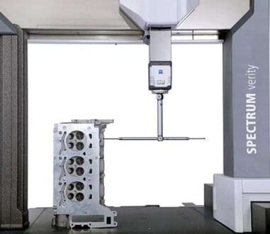
A shop running GD&T-heavy parts through regularly hits the point where sending work out for every batch stops making sense against the day rate. Once volume climbs, buying a CMM outright and running the GD&T checks in-house turns out cheaper than the queue and turnaround of an outside inspection service. The ZEISS CONTURA and PRISMO ranges both handle the positional and profile tolerance work this article’s been describing, and both run on CALYPSO, which means the datum referencing and tolerance calculation logic stays identical whether the part’s measured here or on your own floor. The MICURA is worth a look too if the parts in question are small with tight tolerances, since positional tolerance on a miniature feature needs a probing system built for that scale rather than a general-purpose machine pushed past its comfortable range.

Bring the drawing, not just the part
A GD&T inspection report is only as good as the datum structure it’s built against, and that structure comes from the drawing, not from guessing at design intent off the part itself. Global TechSolutions runs CMM-based GD&T inspection as part of the ZEISS Partner Metrology Centre in Singapore, and also supplies the CONTURA, PRISMO, and MICURA machines directly if the volume in front of you makes more sense to bring in-house. Send the drawing along with the part and we’ll scope the inspection, or the machine, before anything gets probed.
Contact Us for a Free Demo
Whether you need a live demo with your own parts or expert measurement services, our specialists are ready to support your quality assurance needs.