


Measuring the Relationship Between Features, Not Just the Features Themselves
Geometric Dimensioning and Tolerancing is about more than checking whether individual dimensions fall within a numerical range. GD&T inspection evaluates how features relate to datums, axes, planes and one another, turning engineering intent into measurable geometric requirements.
In This Article
- Why GD&T is different from dimensional inspection
- Datums and feature relationships
- Key GD&T characteristics
- How CMM inspection measures GD&T
- The role of ZEISS CALYPSO
- Choosing the right CMM
Why GD&T Is About More Than Individual Dimensions
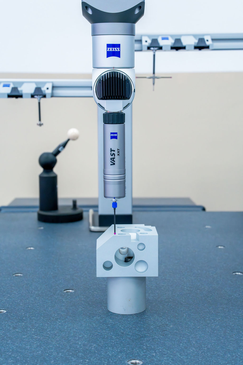
A component can have dimensions that appear correct individually and still fail to assemble, locate or function correctly. The reason is that many engineering requirements describe relationships rather than isolated sizes.
A hole may have the correct diameter but be positioned incorrectly relative to a datum. A surface may be flat enough on its own but not sufficiently perpendicular to another reference surface. Two features may both fall within their dimensional limits while their combined relationship causes an assembly problem.
This is where Geometric Dimensioning and Tolerancing, commonly referred to as GD&T, becomes important. Instead of describing only how large or small a feature may be, GD&T provides a structured way to define form, orientation, location and relationship requirements.
The key idea is simple: GD&T does not only ask whether a feature is the right size. It asks whether that feature exists in the right geometric relationship to the rest of the component.
GD&T Inspection vs Conventional Dimensional Inspection
Conventional dimensional inspection usually starts with direct numerical measurements such as length, diameter, thickness or distance. These values are important, but they do not always describe how a manufactured component will behave when assembled.
GD&T adds another layer by defining the geometric condition that a feature must satisfy. The inspection therefore needs to consider the feature itself, the applicable datum reference system and the tolerance zone specified by the engineering drawing.
| Conventional Dimension | GD&T Requirement | What Inspection Needs to Establish |
|---|---|---|
| Hole diameter | Position | Whether the hole is located correctly relative to the specified datum reference frame. |
| Surface height | Perpendicularity | Whether the surface or feature is oriented correctly relative to its datum. |
| Surface dimensions | Flatness | Whether the entire surface lies within the defined flatness tolerance zone. |
| Two feature locations | Position / orientation relationship | Whether the features maintain the required relationship to the datum system and each other. |
Datums: The Reference Framework Behind GD&T
A GD&T requirement cannot always be understood by looking at the feature in isolation. Many geometric tolerances depend on a datum reference system that establishes how the component should be oriented and located during inspection.
Datums can be derived from physical surfaces, axes or other features identified on the engineering drawing. They provide the reference framework against which other characteristics are evaluated.
Primary Datum
Establishes the first reference plane or feature used to orient the component within the measurement coordinate system.
Secondary Datum
Adds another reference direction or location to further constrain the component and establish the intended inspection orientation.
Tertiary Datum
Completes the datum reference framework and helps establish the remaining location or rotational constraint.
In a CMM inspection, the datum reference system becomes part of the measurement strategy. The machine does not simply collect coordinates. The measured features are evaluated within the appropriate coordinate system so that the resulting GD&T calculation reflects the engineering drawing.
The GD&T Characteristics That CMM Inspection Can Evaluate
GD&T contains a range of geometric characteristics. The appropriate characteristics depend on the component, engineering drawing and intended function of the part.
Position
Defines how accurately a feature such as a hole, pin or slot must be located relative to the specified datum reference system.
Flatness
Controls how much a surface may vary from a theoretically flat condition without relying on a datum reference.
Perpendicularity
Controls the orientation of a feature or surface relative to a specified datum.
Parallelism
Controls whether a surface, axis or feature maintains the required parallel relationship to its reference.
Straightness
Controls the deviation of a line element or feature from its theoretically straight condition.
Roundness
Controls how closely a circular feature conforms to the required round form.
Cylindricity
Evaluates the complete cylindrical form rather than checking diameter at only one or two locations.
Profile
Controls the shape of a surface or line relative to the specified theoretical profile.
Why Feature Relationships Matter in Real Components
The practical value of GD&T becomes clearer when looking at components containing multiple interacting features.
Consider a machined housing with several mounting holes. Measuring each hole diameter may confirm that the holes were manufactured to size. However, the assembly can still fail if the holes are not positioned correctly relative to the mounting face and one another.
The same principle applies to shafts, bearing seats, fixtures, moulds, tooling, semiconductor equipment components and precision mechanical assemblies. Functional performance often depends on relationships between features rather than any single dimension.
- Hole-to-hole position
- Hole-to-datum relationship
- Axis alignment
- Surface orientation
- Parallel surfaces
- Perpendicular features
- Concentric or coaxial relationships
- Profile relative to nominal geometry
How a CMM Measures GD&T
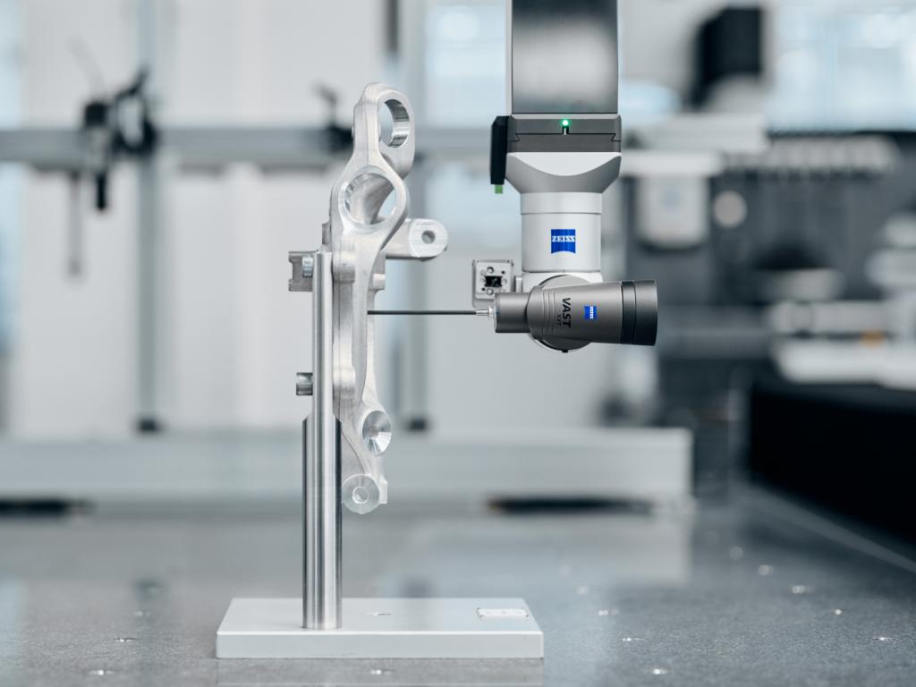
A CMM inspection programme is built around the characteristics that need to be verified. For GD&T, that means the measurement strategy needs to account for the feature geometry, datum structure, tolerance requirement and appropriate sensor configuration.
A Typical GD&T Measurement Workflow
The inspection process moves from the engineering requirement to measured coordinate data and finally to documented results.
- 01 — Read the drawing: Identify the critical dimensions, datums, GD&T symbols and applicable tolerance requirements.
- 02 — Establish the datum system: Define how the component should be oriented and located within the measurement coordinate system.
- 03 — Select the measurement strategy: Determine the appropriate probe, sensor, feature sampling method and measurement sequence.
- 04 — Measure the features: Capture the coordinate data required to establish the relevant geometric characteristics.
- 05 — Evaluate the GD&T: Calculate the applicable characteristics against the specified datum reference frame and tolerance.
- 06 — Report the results: Generate documented measurement results for quality control, first article inspection or production verification.
Sensor Selection Still Matters
Not every GD&T characteristic requires the same measurement strategy. The geometry, size, accessibility and material of the feature all influence the appropriate sensor configuration.
Tactile Probing
Suitable for many defined geometric features such as planes, bores, cylinders, spheres and other discrete characteristics requiring coordinate measurement.
Active Scanning
Captures dense measurement data along a feature or surface and can be useful where a larger quantity of coordinate information is required.
Optical Measurement
For suitable applications, optical sensors can extend the CMM workflow to features and surfaces where non-contact measurement provides useful information.
The Role of ZEISS CALYPSO in GD&T Inspection
The CMM provides the physical measurement capability, but the inspection software is responsible for turning the measurement strategy into an organised inspection workflow.
ZEISS CALYPSO is the CMM software environment used for creating inspection plans, measuring standard geometries and evaluating measurement results.
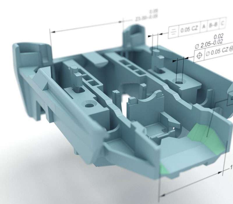
For GD&T inspection, the software workflow connects the measurement plan to the characteristics that need to be evaluated. Depending on the inspection requirement, this can include dimensions, form characteristics, orientation characteristics and location characteristics.
The result is more than a collection of individual measurements. It is a structured inspection record showing whether the measured component satisfies the defined requirements.
Explore ZEISS CALYPSO →Which ZEISS CMM Fits a GD&T Inspection Requirement?
The appropriate CMM depends on the part, measurement volume, tolerances, feature complexity, inspection environment and required sensor configuration. GD&T inspection is therefore an application question rather than simply a machine-selection question.
ZEISS SPECTRUM
A bridge-type CMM platform supporting tactile measurement, scanning workflows and optional optical scanning. It can be configured around dimensional inspection, first article inspection and GD&T verification.
Explore ZEISS SPECTRUM →ZEISS CONTURA
A versatile CMM platform with tactile and optical measurement capabilities. Its sensor flexibility can be useful where a component combines different feature and measurement requirements.
Explore ZEISS CONTURA →ZEISS PRISMO
A reference-class CMM platform for demanding coordinate metrology applications where high measurement performance and advanced scanning capabilities are required.
Explore ZEISS PRISMO →ZEISS CALYPSO
CMM software for creating inspection plans, measuring geometrical elements and evaluating dimensional measurement results within the ZEISS CMM environment.
Explore ZEISS CALYPSO →When CMM Inspection Is the Right Approach
CMM inspection is particularly useful when the engineering requirement is defined around discrete geometric features, dimensional relationships and tolerances that need to be evaluated against a controlled reference system.
- Tight dimensional tolerances
- GD&T verification
- Datum-based inspection
- Hole and bore measurement
- Position verification
- Form and orientation inspection
- First Article Inspection
- Production quality control
CMM vs 3D Scanning for GD&T-Related Inspection
CMM and 3D scanning are not necessarily competing technologies. They provide different types of measurement information and can complement one another when a component contains both discrete features and complex surfaces.
| Requirement | CMM | 3D Scanning |
|---|---|---|
| Defined geometric features | Well suited | Can be suitable depending on geometry |
| Datum-based GD&T | Strong fit | Possible with appropriate software and workflow |
| Dense surface capture | Possible with scanning configurations | Strong fit |
| Freeform surfaces | Possible but measurement strategy is important | Strong fit for full-field surface capture |
| Individual dimensions and tolerances | Strong fit | Possible depending on the inspection workflow |
The right approach depends on what the drawing and inspection requirement are actually asking you to establish. For some components, a CMM provides the most direct route to the required geometric information. For others, a combination of CMM and optical 3D measurement may provide a more complete inspection workflow.
Where GD&T Inspection Is Commonly Used
Precision Manufacturing
Machined components, fixtures, tooling, shafts, housings and other parts where feature relationships directly affect assembly and functional performance.
Equipment Components
Mechanical equipment components where dimensional verification, alignment and tolerance control are important to the wider assembly.
Semiconductor Equipment
Precision components, tooling, fixtures and other manufactured parts where dimensional and geometric requirements need to be verified against engineering specifications.
Electronics
Small and complex components where feature position, geometry, alignment and dimensional consistency can affect assembly.
Automotive
Precision machined and formed components where feature location, orientation and assembly relationships must be controlled.
Aerospace
Components with tightly controlled geometric relationships where dimensional evidence and repeatable inspection are important.
What to Consider Before Selecting a GD&T Inspection System
The machine should be selected after the inspection requirement is understood. Starting with the CMM model and working backwards can lead to a configuration that does not match the actual measurement task.
Start With the Part
The following questions help define the measurement requirement before selecting the CMM and sensor configuration.
- What features need to be measured? Identify holes, planes, cylinders, slots, profiles, axes and other critical characteristics.
- What GD&T characteristics are specified? Determine whether the drawing calls for position, flatness, perpendicularity, parallelism, profile or other controls.
- What are the datum references? Understand how the component is intended to be located and oriented during inspection.
- How large is the component? The required measurement volume influences the appropriate CMM configuration.
- How accessible are the features? Feature accessibility can influence probe configuration, indexing requirements and measurement strategy.
- Is optical measurement also required? Some components may benefit from a multisensor or scanning configuration alongside tactile measurement.
- How will the results be documented? Consider whether the inspection requires a structured dimensional report, FAI documentation or recurring production inspection.
Related Metrology Resources
GD&T inspection often sits within a wider dimensional measurement workflow. These related GTS resources provide additional context on CMMs, applications and measurement technologies.
Frequently Asked Questions About GD&T Inspection
GD&T inspection verifies geometric characteristics defined by an engineering drawing, including the relationship between features, surfaces, axes and specified datum references. A CMM can measure the required coordinates and evaluate the resulting characteristics against their tolerances.
A dimensional measurement can establish whether a feature is within a size requirement. GD&T can additionally establish whether the feature has the required form, orientation or location relative to a datum reference system or another feature.
Yes. CMMs can measure the coordinates of appropriate features and use the applicable datum reference system to evaluate position requirements specified on the engineering drawing.
CMMs can evaluate many form and orientation characteristics, including flatness and perpendicularity, provided the part, measurement strategy, sensor configuration and drawing requirements are appropriate for the inspection.
ZEISS CALYPSO is the CMM software environment used for inspection planning, dimensional measurement and evaluation of geometrical elements within ZEISS CMM workflows.
The appropriate system depends on the component size, tolerance requirements, feature complexity, sensor requirements and inspection environment. ZEISS SPECTRUM, CONTURA and PRISMO are examples of CMM platforms within the current GTS portfolio, with different configurations suited to different measurement requirements.
GD&T Turns Measurement Into Functional Evidence
A precision component is rarely defined by dimensions alone. Its function often depends on how its features relate to one another and to the datum reference system defined by the engineering design.
That is why GD&T inspection requires more than checking whether a collection of dimensions falls within tolerance. The inspection needs to establish the correct measurement reference, capture the relevant geometry and evaluate the relationship described by the drawing.
A CMM provides a controlled way to capture coordinate data from defined features, while software such as ZEISS CALYPSO provides the inspection environment for planning and evaluating the resulting measurements.
The most appropriate measurement system ultimately depends on the part and the inspection problem. For components dominated by discrete dimensional and geometric requirements, CMM inspection can provide the structured measurement data needed to verify GD&T requirements. Where complex surfaces or additional information are involved, tactile, optical and scanning technologies can also be combined into a wider metrology workflow.
The objective of GD&T inspection is not simply to measure more features. It is to produce measurement data that reflects how the component was actually designed to function.
Explore our metrology solutions.
Download our portfolio to explore our ZEISS industrial metrology solutions, measurement technologies and applications for demanding manufacturing environments.
GTS Metrology Portfolio
Get an overview of our solutions, capabilities and industrial metrology applications.
Download Portfolio ↓Have a part you need to measure?
Bring us your measurement challenge. Discuss your component, tolerance requirements and inspection objectives with our metrology specialists.