

Industrial CT Scanner: What It Actually Reveals Inside Your Parts
Field failures and incoming inspection rejections cost time when root causes remain hidden inside castings or moulded housings. Traditional destructive analysis, such as sectioning or layer-by-layer grinding, destroys the evidence required for diagnosis. Industrial CT scanning eliminates this limitation through non-destructive volumetric inspection.
What’s actually happening inside the machine
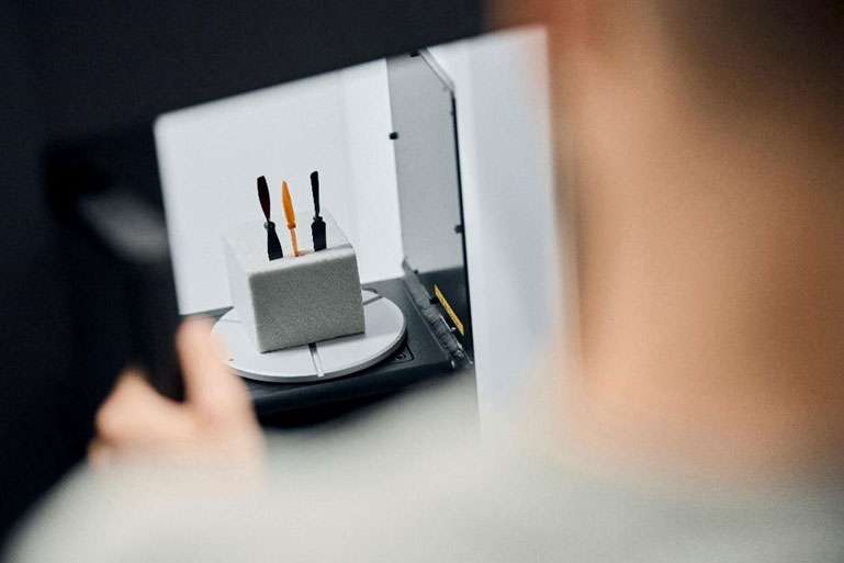
An industrial CT scanner fires X-rays through a rotating part and records how much radiation makes it to the detector on the other side. Dense material blocks more of the beam. Air, voids, and lighter materials block less. The scanner captures a projection at every few tenths of a degree across a full rotation, often several thousand of them for a high resolution run, and reconstruction software stitches those projections into a voxel-based volume. Every voxel carries a grey value tied to material density at that point in space.
That is the whole trick. No probe touches the part. No sectioning happens. You get a complete internal and external map of the component from a single scan, and you can slice through it in any plane afterwards without ever picking up a saw.
Compare that to a tactile CMM, which only tells you about the surface points the probe physically reached, or an optical 3D scanner, which is blind to anything the camera can’t see. CT does not care what’s hidden behind a wall of aluminium or buried inside a sealed housing. It sees straight through it.

Where this earns its keep on the shop floor
Porosity analysis in castings is the obvious one. Aluminium die castings and investment castings trap gas during solidification, and those voids weaken the part in ways a surface inspection will never catch. A CT scan quantifies porosity as a percentage of volume and locates every void in three dimensions, which means you stop guessing whether a batch is scrap or salvageable.
Plastic injection moulded parts have their own headaches. Wall thickness variation causes warpage, sink marks, and inconsistent shrinkage, and CT measures wall thickness throughout the part rather than at the handful of points a caliper or a CMM stylus can physically reach. For multi-material assemblies, plastic connectors with metal inserts being a common example, a single CT scan checks both materials at once without disassembly.
Electronics inspection is where CT earns its money fastest. Solder joints hide under ball grid arrays. Voids inside those joints cause intermittent failures that show up months after shipment, not on the test bench. CT catches the void before the board leaves the building.
Then there’s reverse engineering. When you’ve got a legacy part with no CAD file, industrial CT captures internal and external geometry in one pass, giving you the full dataset needed to rebuild a usable model. A surface scanner alone leaves you guessing at internal features you can’t see.
The kV question nobody explains properly
Buyers get hung up on resolution numbers in the brochure and skip past the one variable that decides whether the machine can even scan their parts: tube voltage. A 130 kV system handles small to medium plastic components at high throughput and gives you excellent dimensional accuracy, but it will not penetrate a solid steel bracket. Push into 225 kV and you’re covering small plastic parts through medium mixed-material assemblies. Go to 320 kV, and now you’re punching through dense metal parts that would choke a lower power tube entirely.
This is not a spec you round up on and hope for the best. If your parts run from thin polymer housings to solid steel forgings, no single tube voltage covers that whole range well. You either pick the system that matches your dominant part mix or you accept that some jobs go to an outside lab.
Resolution and voxel size matter just as much, and they’re often confused with each other. Voxel size is the physical dimension each measurement point represents in the reconstructed volume, and it drives how fine a defect the scan can actually resolve. A system with sub-micron capability is built for small, dense, high-value components where a five micron void changes the failure risk profile. If you’re scanning aerospace castings the size of a dinner plate, that same sub-micron voxel size just means an unnecessarily long scan time for no practical gain.
What separates a real result from a pretty picture
Anyone can generate a colourful volumetric render. Getting a measurement result you can defend in front of a customer is a different job entirely.
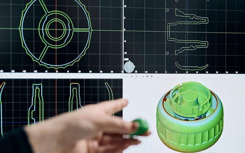
Nominal-actual comparison against a CAD model is the piece people underestimate. A raw CT volume tells you what the part looks like. It takes proper analysis software to overlay that volume against the design intent and produce a colour-coded deviation map you can actually act on. Skip that step and you’ve bought an expensive way to look at a part without learning anything you can put in a report.
Turnaround time is where a lot of buyers get burned after the sale. Scan time on the machine is only part of the story. Reconstruction, analysis, and reporting all take bench time from a trained operator, and a provider promising same-day results on a complex multi-material assembly is usually cutting corners somewhere in that chain. ZEISS CT measuring services commit to three working days on standard jobs, frequently faster, and that number holds because the workflow between scan and report is built to support it rather than bolted on afterwards.
Buying versus outsourcing
A full industrial CT installation is not a small commitment. Beyond the machine cost, you’re looking at radiation shielding requirements, a dedicated space with controlled temperature, and an operator who actually understands reconstruction artefacts well enough to tell a genuine void from a beam hardening error. For a manufacturer running high volumes of the same part family through CT inspection every week, owning the system pays for itself. For everyone else, particularly anyone doing first article inspection on a handful of new part numbers a month, a CT measuring service gets you the same data without the capital outlay or the compliance headache of running an X-ray source in-house.
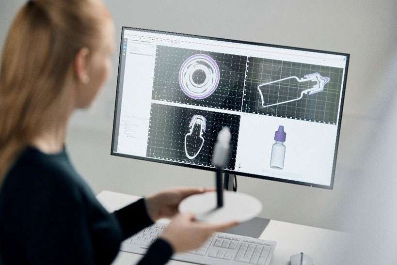
Book a demo with your own parts
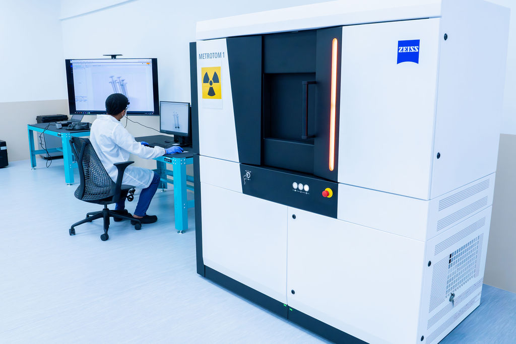
In Singapore, that service sits at Global TechSolutions, the ZEISS Partner Metrology Centre for the region, running the same METROTOM hardware covered above. Book a scan with your own part and see what turns up.
Our Industrial CT Scanners
Our lineup of ZEISS X-ray systems is engineered to handle your specific application and measurement needs:
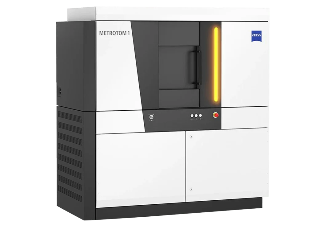
ZEISS METROTOM 1
Designed for your measuring lab, this system easily uncovers hidden workpiece defects. Ideal for small-to-medium plastic or light-metal components (such as connectors, caps, and aluminum parts), it excels at performing accurate nominal-versus-actual comparisons, dimensional checks, and wall thickness analyses.
Part Parameters:
-
Max Measuring Range – Diameter: 165 mm
-
Max Measuring Range – Height: 140 mm
- Max Part Weight: 5 kg
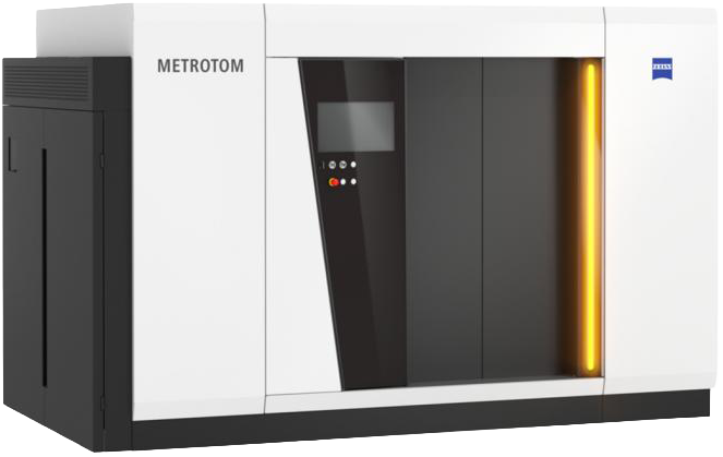
ZEISS METROTOM 800 225kV
Featuring a High-Resolution option, the 225 kV version of the ZEISS METROTOM 800 meets rigorous high-precision inspection standards. It is specifically optimized for denser materials and rapid, high-speed scanning.
Part Parameters:
-
Max Diameter: 300 mm
-
Max Height: 360 mm
-
Max Weight: 5 kg
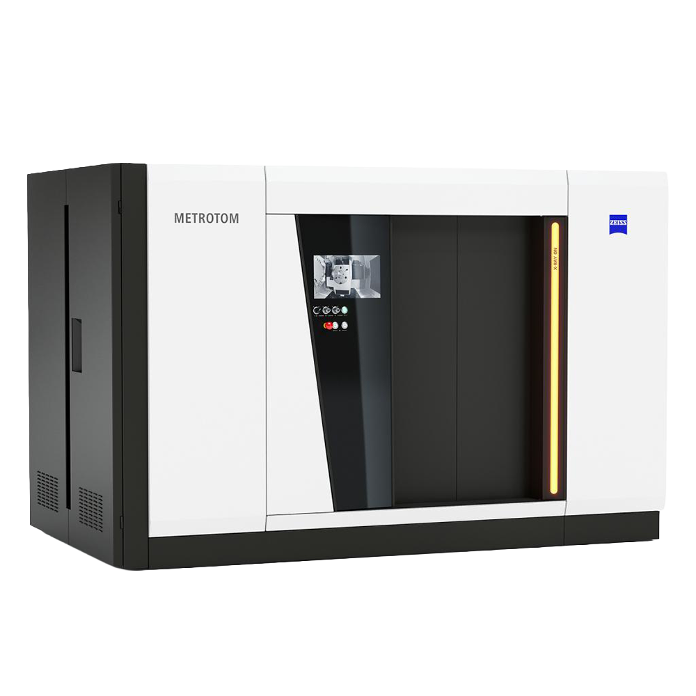
ZEISS METROTOM 800 / 320 kV
Engineered specifically for high-density, challenging materials (such as Inconel, Cobalt Chromium, additively manufactured metal components, and multi-material assemblies). Driven by a robust 320 kV micro-focus tube and up to 500 W of power, this system achieves optimal X-ray penetration and reliable quality assurance for demanding aerospace, medical, and automotive applications without sacrificing speed.
Part Parameters:
-
Max Measuring Range / Reconstruction Volume (Standard): Diameter: 325 mm × Height: 250 mm (Scalable up to 500 mm × 470 mm with field-of-view extensions)
-
Max Part Weight: 50kg
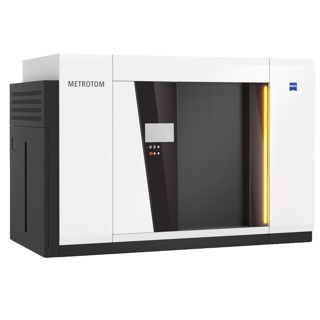
ZEISS METROTOM 1500 (with ZEISS scatterControl)
Built with a high-resolution 3k detector, this system captures detailed 3D volume data to reveal minute internal features. Integrated with ZEISS scatterControl, it drastically improves image quality while minimising scatter artifacts during CT scans.
Part Parameters:
-
Max Diameter: 615 mm
-
Max Height: 800 mm
-
Max Weight: 50 kg
Contact Us for a Free Demo
Whether you need a live demo with your own parts or expert measurement services, our specialists are ready to support your quality assurance needs.