
3D Scanner Supplier in Singapore: What You’re Actually Buying
Choosing a 3D scanner is not simply a matter of comparing scanner specifications and prices. For manufacturers, the more important question is whether the system can produce the measurement data you need and fit into your existing inspection process.

In This Article
- What a 3D Scanner Supplier Should Provide
- Not Every 3D Scanner Does the Same Job
- Choosing the Right Scanning Technology
- ZEISS 3D Scanner Solutions
- From Scan Data to Inspection Results
- Why Local Support Matters
- What to Ask Before Buying
- Choosing a 3D Scanner in Singapore
What Should a 3D Scanner Supplier Provide?
A professional 3D scanning solution should cover more than the scanner hardware.
When manufacturers evaluate an industrial 3D scanner, it is easy to focus on the equipment specification. Resolution, accuracy, scanning speed and field of view are all important, but they only describe part of the solution.
The supplier also needs to understand how the scanner will actually be used. The same system may be suitable for one component but inappropriate for another because of differences in part size, geometry, surface condition, required accuracy or inspection workflow.
-
3D scanner selection
Matching the scanner to the component and inspection requirements. -
Application evaluation
Reviewing the part, geometry and measurement objective before selection. -
Live demonstrations
Testing the technology using the customer’s actual component. -
Inspection software
Turning captured scan data into usable measurement and inspection results. -
System setup
Configuring the equipment for its intended measurement workflow. -
Operator training
Helping users understand both scanning and downstream inspection. -
Technical support
Providing assistance when applications or inspection requirements change. -
Workflow integration
Connecting 3D scanning with existing quality-control processes.
A scanner may capture millions of measurement points, but those measurements are only useful if they can be reliably captured, analysed and compared against the required engineering or quality criteria.
Not Every 3D Scanner Is Designed for the Same Job
Industrial 3D scanners are designed around different measurement requirements. A handheld laser scanner, a structured-light system and an automated scanning setup can all produce 3D measurement data, but their strengths and practical workflows can be very different.
Before comparing specific models, start with the component.
Part Size
Small precision components and large industrial structures can require very different scanning configurations, working distances and reference strategies.
Geometry
Freeform surfaces, deep features, sharp edges and complex assemblies can influence how easily the geometry can be captured.
Surface
Dark, shiny, reflective or otherwise challenging surfaces can affect the practical scanning workflow and may require an appropriate system or preparation method.
Accuracy
Required measurement performance should be determined by the actual inspection requirement rather than simply selecting the highest specification available.
Inspection Volume
Occasional inspection of individual components can have very different requirements from repeatable production inspection.
Portability
Large or difficult-to-move components may benefit from a portable scanner that can be taken directly to the component.
The objective should therefore be to match the scanner to the application rather than simply selecting the scanner with the highest advertised specification.
Choosing the Right ZEISS 3D Scanner
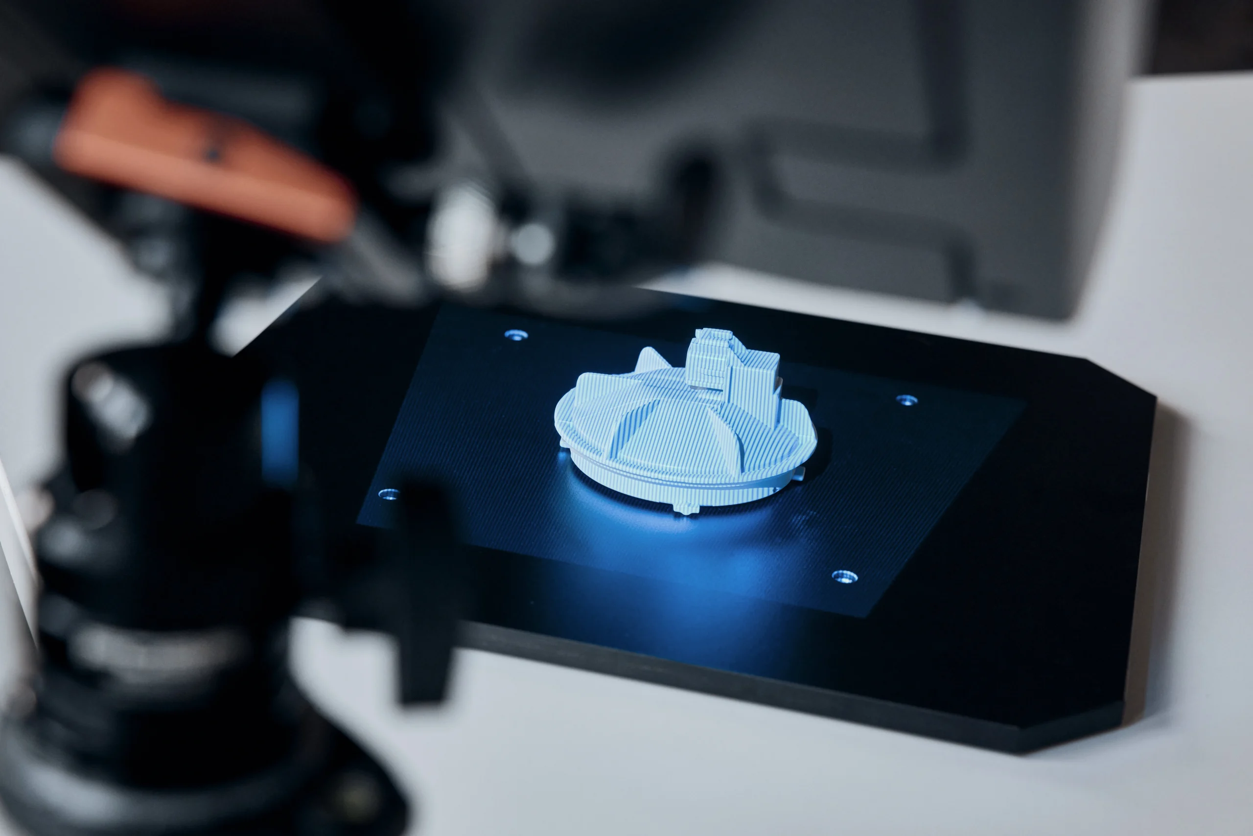
GTS provides access to a range of ZEISS industrial 3D scanning solutions for different inspection and measurement requirements. The right choice depends on what needs to be measured, how the component needs to be accessed and how the resulting data will be used.
ZEISS T-SCAN hawk 2
A handheld 3D laser scanner designed for flexible measurement tasks. Its portable format allows users to bring 3D scanning directly to the component, including larger parts and difficult-to-access areas.
Typical applications include dimensional inspection, CAD comparison, component assessment, MRO and reverse-engineering workflows.
View T-SCAN hawk 2ZEISS ATOS Q
An optical 3D measurement system designed for complex inspection tasks involving small to medium-sized components. It captures full-field measurement data for analysing complex geometry and dimensional deviations.
Applications include CAD comparison, dimensional inspection, tooling and mould validation, first article inspection and surface or freeform inspection.
View ATOS QZEISS GOM Scan 1
A compact optical 3D scanning solution for straightforward measurement of small to medium-sized components.
It can support dimensional measurement, CAD comparison, product development, plastic component inspection, electronics and precision component inspection and 3D documentation.
View GOM Scan 1ZEISS INSPECT
3D scanning becomes considerably more useful when the captured data can be processed and analysed effectively. ZEISS INSPECT supports workflows including scan processing, inspection, CAD comparison and deviation analysis.
The software connects captured 3D data with the inspection and engineering decisions that follow.
View ZEISS INSPECT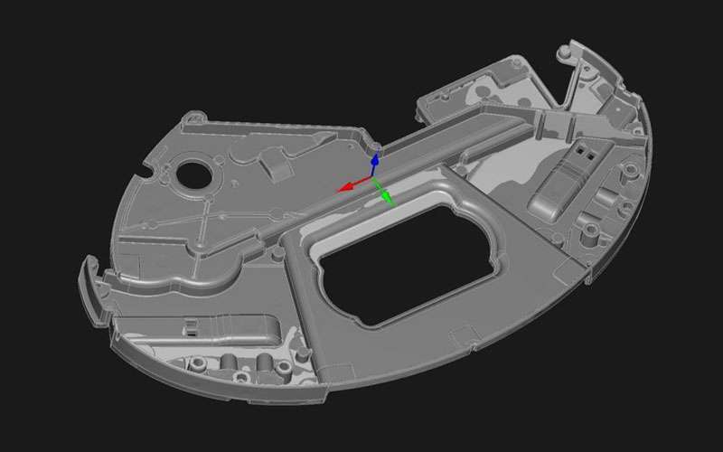
3D Scanning Is More Than Capturing a 3D Model
One of the biggest mistakes when evaluating a 3D scanner is focusing only on the scanning process.
For industrial inspection, the important step comes after the scan. The captured data needs to become usable information that engineers, quality teams and production teams can interpret.
CAD Comparison
Scan data can be compared against the original CAD model to identify deviations across the complete surface of a component. This provides a broader view of how the manufactured part differs from its nominal geometry.
Dimensional Inspection
3D scan data can be used to evaluate dimensions, geometric features and surface deviations across complex components rather than relying only on selected measurement points.
First Article Inspection
For new or modified components, 3D scanning can help verify manufactured parts against design requirements before full production begins.
Reverse Engineering
3D scanning can form part of a reverse-engineering workflow where existing component geometry needs to be captured and converted into usable digital data.
Why Local Support Matters When Buying a 3D Scanner in Singapore
For companies purchasing industrial metrology equipment, local technical support can be just as important as the scanner itself.
A 3D scanner is not normally purchased in isolation. The system needs to work with the components being inspected, the operators using it and the quality-control workflow in which the resulting data will be applied.
Application Assessment
Your actual parts and inspection requirements can be reviewed before selecting a system.
Product Demonstration
Testing the scanner with your own component can provide a clearer indication of whether the technology is suitable.
System Setup
The scanner needs to be configured appropriately for the intended measurement and inspection workflow.
Training
Operators need to understand not only how to capture scans, but how to create reliable inspection results from the data.
Technical Support
Local technical support can help when application requirements change or new inspection challenges arise.
Application Development
As inspection requirements evolve, application support can help adapt the measurement workflow to new parts and requirements.
Where Industrial 3D Scanning Can Be Applied
3D scanning can support different manufacturing and inspection requirements across the GTS ZEISS application portfolio.
Equipment Components
Complex industrial equipment components can benefit from dimensional verification, CAD comparison and legacy-part digitisation.
Explore Equipment Component Metrology →Plastic Manufacturing
Optical 3D scanning can help evaluate warpage, shrinkage, dimensional variation and moulded component geometry.
Explore Plastic Manufacturing Metrology →Metal Processing
Large, freeform and complex metal components can be measured and compared against their nominal CAD geometry.
Explore Metal Processing Metrology →Aerospace & MRO
Portable 3D scanning can support inspection of large and complex aerospace and MRO components where access and component size are important considerations.
Explore Aerospace Metrology →Electronic Components
Small and complex electronic components can require detailed dimensional and surface inspection.
Explore Electronic Component Metrology →Cable & Connectors
Connector and cable components can be inspected for dimensional characteristics and complex geometry.
Explore Cable & Connector Metrology →
What to Ask a 3D Scanner Supplier Before Buying
Before purchasing a 3D scanner, the most useful questions are usually about your application rather than the equipment specification alone.
How to Choose a 3D Scanner in Singapore
The right 3D scanner depends on what you need to measure, how often you need to measure it and how the resulting data will be used.
Start With the Measurement Requirement
-
What are you measuring?
Identify the component, material, size, geometry and critical features. -
What measurement performance is required?
Establish the required accuracy and repeatability from the actual application. -
How large is the component?
A large industrial component may require a different scanning approach from a small precision part. -
How complex is the geometry?
Freeform surfaces, deep features and difficult access can affect scanner selection. -
How important is portability?
Large or difficult-to-move components may benefit from a handheld measurement system. -
What will happen to the scan data?
Determine whether you need CAD comparison, dimensional inspection, deviation analysis, first article inspection or reverse-engineering workflows. -
How often will the system be used?
Occasional inspection and high-volume production measurement can have different requirements.
The Scanner Is Only One Part of the Inspection Workflow
Capturing 3D data is the beginning of the process. The value of that data comes from being able to process it, align it, compare it and turn it into meaningful inspection information.
ZEISS INSPECT
ZEISS INSPECT provides a software environment for processing and analysing 3D measurement data. It supports inspection workflows such as scan processing, CAD comparison, dimensional analysis and reporting.
Explore ZEISS INSPECTZEISS CALYPSO
ZEISS CALYPSO is designed for dimensional measurement workflows with ZEISS CMM systems. It is particularly relevant when defined features and geometric characteristics need to be measured using a CMM.
Explore ZEISS CALYPSOWhat You’re Actually Buying From a 3D Scanner Supplier
A 3D scanner is only one part of an industrial measurement solution.
The scanner needs to be appropriate for the component. The measurement method needs to suit the geometry and required accuracy. The software needs to turn captured data into useful inspection information. The workflow needs to fit the quality process. And the supplier needs to be able to support the application beyond the initial purchase.
For some applications, a handheld system such as the ZEISS T-SCAN hawk 2 provides the flexibility required for large or difficult-to-access components. For complex small-to-medium-sized parts, the ZEISS ATOS Q provides full-field optical measurement capabilities. For straightforward measurement of smaller components, the ZEISS GOM Scan 1 offers a compact scanning solution.
The starting question therefore should not simply be:
“Which 3D scanner should I buy?”
It should be:
“What do I need to measure, and what inspection result do I need from that measurement?”
That distinction can make the difference between buying a scanner and implementing a measurement solution that actually works for your manufacturing process.
Explore our metrology solutions.
Download our portfolio to explore our ZEISS industrial metrology solutions, measurement technologies and applications for demanding manufacturing environments.
GTS Metrology Portfolio
Get an overview of our solutions, capabilities and industrial metrology applications.
Download Portfolio ↓Have a part you need to measure?
Bring us your measurement challenge. Discuss your component, tolerance requirements and inspection objectives with our metrology specialists.