


CMM vs. 3D Scanning: Choosing the Right Inspection Technology for Your Parts
CMMs and 3D scanners both provide detailed measurement data, but they answer different inspection questions. The right choice depends on the part geometry, tolerances, accessibility, inspection workflow and type of information required.
In This Article
- CMM and 3D scanning explained
- Key differences between the technologies
- Accuracy and dimensional measurement
- GD&T and defined geometric features
- Freeform surfaces and full-field inspection
- CAD comparison and reverse engineering
- Part size, accessibility and complexity
- ZEISS CMM and 3D scanning solutions
CMM and 3D Scanning Solve Different Measurement Problems
Choosing between a coordinate measuring machine and a 3D scanner is not simply a question of which technology is more accurate. Both can produce highly useful measurement data, but they collect and present that information differently.
A CMM is particularly suited to measuring defined geometric features, dimensions and relationships between features. It is commonly used where engineering drawings specify datums, tolerances and GD&T requirements.
A 3D scanner is more naturally suited to capturing a large amount of surface information. Instead of selecting individual points, optical scanning can generate a dense representation of the part that can be used for surface inspection, CAD comparison and reverse engineering.
The decision should therefore start with the inspection requirement rather than the equipment. What needs to be measured? Which features matter? Are they accessible? Is the requirement based on individual dimensions or the complete surface?
What Is a Coordinate Measuring Machine?
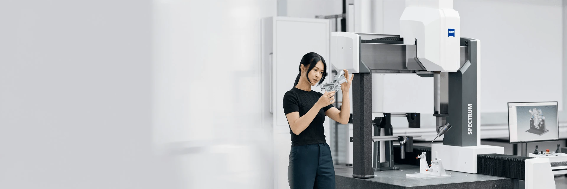
A coordinate measuring machine, or CMM, measures the physical location of features in three-dimensional space. Depending on the configuration, a CMM can use tactile probes, scanning systems or optical sensors to collect measurement data.
For conventional dimensional inspection, the machine establishes a coordinate system and measures defined features relative to datums. The resulting data can then be evaluated against drawings, CAD models and specified tolerances.
Defined Dimensions
CMMs are well suited to measurements such as diameters, distances, angles, hole locations and feature positions.
GD&T
Geometric relationships such as flatness, parallelism, perpendicularity, position and form can be evaluated within an established datum structure.
Repeatable Inspection
Defined inspection routines can be repeated across production parts, supporting quality control and comparison between batches.
CMM inspection is therefore particularly useful when the engineering requirement is expressed through specific dimensions and geometric tolerances rather than a complete surface representation.
A useful rule: when the inspection question is primarily about defined features, datums and geometric relationships, a CMM is often a natural starting point.
What Is 3D Scanning?
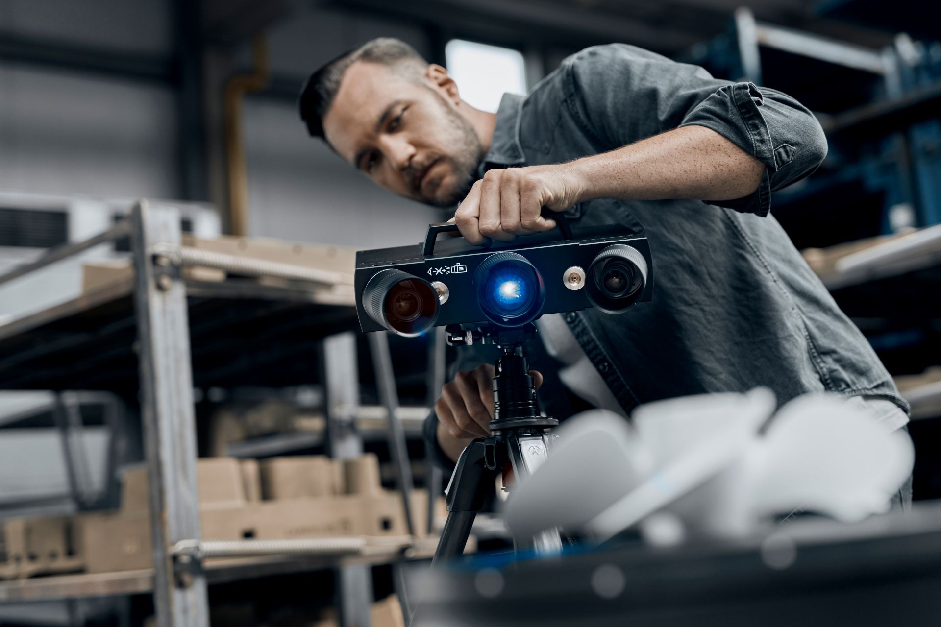
Optical 3D scanning captures the surface geometry of a physical component and converts it into digital three-dimensional data. Depending on the system, this may be generated using structured light, fringe projection or laser scanning.
Instead of measuring only selected points, a scanner can capture a dense collection of points across the surface. This makes the technology particularly useful for complex shapes, freeform surfaces and applications where the complete geometry needs to be understood.
Full-Field Surface Inspection
A scan can capture the complete accessible surface rather than relying on a limited number of individual measurement points.
Complex Geometry
Freeform surfaces, curved profiles and complex external shapes can be represented as dense three-dimensional data.
CAD Comparison
Scan data can be aligned with nominal CAD geometry to visualise dimensional deviations across the surface.
Reverse Engineering
Physical parts can be digitised to support the creation or reconstruction of digital geometry where appropriate.
Optical scanning therefore becomes particularly useful when the inspection requirement involves understanding the overall shape rather than only a small number of predefined features.
CMM vs 3D Scanning: What Is the Main Difference?
The simplest way to distinguish the technologies is to consider how the measurement question is framed.
| Inspection Requirement | CMM | 3D Scanning |
|---|---|---|
| Defined dimensions | Strong fit for individual dimensions and feature locations. | Can derive dimensional information from scan data. |
| GD&T | Particularly suited to defined geometric tolerances and datum relationships. | Suitable for many geometric inspection workflows when supported by the software and measurement strategy. |
| Freeform surfaces | Possible, but inspection strategy may require carefully selected measurement points. | Well suited to dense surface capture and full-field analysis. |
| CAD comparison | Can compare measured features against nominal geometry. | Particularly useful for colour maps and dense surface deviation analysis. |
| Individual critical features | Well suited to targeted feature measurement. | Features can be evaluated from captured surface data where accessible. |
| Complete external surface | Requires a defined measurement strategy. | Strong fit for dense surface capture. |
| Reverse engineering | Can provide highly controlled dimensional information. | Particularly useful for digitising physical surface geometry. |
| Hidden internal features | Limited by physical probe access. | Limited to accessible surfaces; CT may be more appropriate for internal geometry. |
Neither technology is a universal replacement for the other. The appropriate system depends on the geometry being inspected, the required information and how that information will be used.
Accuracy Is Only One Part of the Decision
Accuracy is often the first specification considered when comparing inspection technologies, but accuracy alone does not determine whether a system is suitable for an application.
A measurement system needs to provide appropriate accuracy and repeatability for the tolerance being inspected. At the same time, the measurement strategy needs to capture the relevant geometry correctly.
For example, a part may contain a complex freeform surface with a localised deviation. Measuring a small number of discrete points may not provide the same information as capturing the surface densely and comparing it against nominal CAD.
Conversely, a component drawing may define a series of critical hole positions, datum relationships and geometric tolerances. In that situation, a structured CMM inspection routine may provide a more direct route to the required measurement results.
Start With the Measurement Requirement
- Defined feature: Determine the size, location, form or orientation of the feature.
- GD&T requirement: Establish the datum structure and geometric relationship that needs to be verified.
- Freeform surface: Consider whether complete surface information is required.
- CAD comparison: Determine whether a deviation map or nominal-to-actual comparison is required.
- Accessibility: Check whether the critical areas can physically be reached by the selected measurement system.
- Inspection frequency: Consider whether the process is intended for one-off analysis, FAI or recurring production inspection.
When GD&T and Defined Features Matter
Geometric dimensioning and tolerancing describes how features relate to one another, not simply whether an individual dimension falls within a numerical range.
A component can have the correct diameter and length but still fail its functional requirement if a hole is positioned incorrectly relative to its datum structure, or if two surfaces are not sufficiently parallel.
This is one area where CMM inspection can be particularly valuable. The machine can establish the required coordinate system and evaluate defined geometric relationships against the inspection requirements.
- Flatness
- Parallelism
- Perpendicularity
- Position
- Straightness
- Roundness
- Profile
- Feature location
When Full-Field 3D Surface Data Matters
Some components are easier to understand when the complete surface is captured rather than reduced to a collection of individual points.
This is especially relevant for freeform or highly curved components, moulded parts, complex housings and other geometries where the location of a deviation may not be known in advance.
Optical 3D scanning can capture a dense representation of the accessible surface. The resulting data can then be inspected against CAD geometry to identify patterns of deviation across the part.
Warpage
Surface deformation can be visualised across a component rather than assessed only at predefined locations.
Shape Deviation
Scan-to-CAD analysis can show where the manufactured geometry differs from the nominal design.
Complex Profiles
Curved and freeform surfaces can be captured as dense three-dimensional data for subsequent analysis.
Reverse Engineering
Physical components can be digitised where a usable digital representation needs to be created from existing geometry.
Part Size, Complexity and Accessibility
The physical characteristics of the part can also influence the measurement method.
A large component may benefit from a portable scanning approach that can be brought directly to the part. A smaller precision component may be better suited to a controlled CMM inspection environment or a compact optical scanner.
Accessibility matters as well. A measurement method may be highly capable in principle but unsuitable if the critical feature cannot be reached, seen or captured reliably.
Controlled Feature Measurement
Suitable where important features can be reached by the probe and where dimensional or geometric relationships are clearly defined.
Surface Capture
Useful when the accessible external surface is complex and a dense representation of the geometry is required.
Internal Geometry
Where important features are hidden inside a component, industrial CT may provide visibility that conventional external measurement cannot.
Inspection Speed Depends on the Application
It can be tempting to compare CMMs and scanners purely on measurement speed, but the complete inspection workflow matters more than a single acquisition figure.
A CMM inspection routine can be highly efficient when the same defined features need to be measured repeatedly. Once the inspection plan is established, the same measurement strategy can be applied consistently across production parts.
3D scanning can be efficient when many surface characteristics need to be captured at once, particularly where a dense surface dataset would otherwise require numerous individual measurement points.
Preparation, fixturing, alignment, accessibility, data processing and reporting all contribute to the total inspection workflow.
CAD Comparison: CMM vs 3D Scanning
Both technologies can support CAD-based inspection, but they are commonly used in different ways.
With a CMM, defined features can be measured against nominal CAD geometry or an engineering drawing. This approach is useful when the inspection requirement is based around specific dimensions, datums and tolerances.
With optical 3D scanning, the captured surface can be aligned with nominal CAD data to generate a dense comparison across the accessible geometry. This can make localised deviations and overall shape differences easier to identify.
| CAD Inspection Requirement | CMM | 3D Scanning |
|---|---|---|
| Defined dimensions | Direct feature-based measurement. | Dimensions can be derived from captured geometry. |
| Feature position | Strong fit for controlled datum-based inspection. | Can evaluate accessible geometry from scan data. |
| Freeform surface | Requires an appropriate measurement strategy. | Dense surface data supports full-field comparison. |
| Deviation map | More commonly focused on defined measured features. | Particularly useful for colour-map and surface deviation workflows. |
What About Reverse Engineering?
Reverse engineering is another area where 3D scanning can be particularly useful because the starting point is often a physical object rather than a complete CAD model.
A scanner can capture the accessible surface geometry and create digital measurement data that can subsequently be processed into usable CAD information.
CMM measurement can also contribute valuable dimensional information, particularly where specific critical features need to be established accurately.
In practice, the two approaches can complement one another depending on the component and the level of detail required.
When Neither CMM nor 3D Scanning Is Enough
CMMs and optical scanners are primarily external measurement technologies. If the critical geometry is located inside a component, physical access can become the limiting factor.
Industrial CT can address a different inspection requirement by generating volumetric data that provides visibility into internal and external structures without cutting the component apart.
ZEISS METROTOM 1
A compact industrial CT system for non-destructive inspection of internal and external component geometry, including hidden structures, wall thickness and defects.
View METROTOM 1Industrial CT Inspection
CT can be considered when the inspection requirement includes internal channels, voids, porosity, wall thickness or other hidden geometry.
Learn About Industrial CTThis is why CMM, 3D scanning and CT should not necessarily be viewed as competing technologies. They can form complementary parts of a broader inspection strategy.
ZEISS Solutions for CMM and 3D Scanning
Global TechSolutions provides access to a range of ZEISS industrial metrology technologies in Singapore. The appropriate system depends on the inspection requirement, part geometry, tolerances and workflow.
ZEISS SPECTRUM
A bridge-type CMM suited to dimensional inspection, defined geometric features and precision manufacturing applications.
View ZEISS SPECTRUMZEISS ATOS Q
An industrial optical 3D measurement system suited to capturing detailed surface geometry and supporting dimensional inspection and CAD comparison.
View ZEISS ATOS QZEISS T-SCAN hawk 2
A handheld 3D laser scanning system designed for portable industrial measurement, quality control and reverse engineering workflows.
View T-SCAN hawk 2GOM Scan 1
A compact structured-light 3D scanner for dimensional inspection, CAD comparison and reverse engineering of small to medium-sized components.
View GOM Scan 1Which Technology Fits Your Part?
The best starting point is the inspection requirement. The following examples provide a practical way to narrow the options.
Precision Machined Parts
Where the inspection focuses on holes, diameters, distances, datums and GD&T, a CMM may provide the most direct measurement workflow.
Freeform Components
Where the shape itself is the primary inspection concern, optical 3D scanning can provide dense surface information for comparison and analysis.
Large Components
Portable 3D scanning can be useful where bringing a large component into a fixed inspection environment is impractical.
Small Detailed Components
Compact optical systems can provide detailed surface data while remaining suitable for smaller components and controlled inspection environments.
First Article Inspection
CMMs and optical 3D systems can both contribute to FAI depending on whether the inspection is centred on defined characteristics or broader surface geometry.
Hidden Internal Features
When important geometry cannot be reached externally, industrial CT should be considered as an alternative inspection method.
A Practical Framework for Choosing Between CMM and 3D Scanning
Rather than starting with the machine, start with the information that the inspection needs to produce.
Six Questions to Ask
- 1. What features are critical? Identify the dimensions, surfaces, holes, datums and geometric relationships that determine whether the part meets specification.
- 2. Is the geometry defined or freeform? Defined engineering features often lend themselves to CMM inspection, while complex freeform surfaces may benefit from dense optical scanning.
- 3. Do you need the whole surface? If the objective is to understand overall surface deviation, full-field 3D scanning can provide useful information.
- 4. Do you need GD&T results? If the inspection centres on datum relationships and geometric tolerances, a CMM may provide a direct workflow.
- 5. Can the critical areas be accessed? Physical accessibility should be considered before selecting the measurement technology.
- 6. Is anything important hidden inside the part? If so, neither conventional external CMM probing nor optical scanning may provide the required visibility, making CT a potential option.
Frequently Asked Questions
CMM vs 3D Scanning: Start With the Inspection Question
The choice between a CMM and a 3D scanner should not be based on a simple assumption that one technology is universally better than the other.
CMMs are well suited to defined dimensional and geometric requirements, particularly where datums, GD&T and feature relationships are central to the inspection.
3D scanning is particularly useful when the inspection requires dense surface information, complex geometry, CAD comparison or reverse engineering of accessible external surfaces.
When important features are hidden inside a component, industrial CT introduces another option by providing non-destructive access to internal and external geometry.
The right question is not simply “CMM or 3D scanner?” It is “What measurement data does this part and inspection requirement actually require?”
Explore our metrology solutions.
Download our portfolio to explore our ZEISS industrial metrology solutions, measurement technologies and applications for demanding manufacturing environments.
GTS Metrology Portfolio
Get an overview of our solutions, capabilities and industrial metrology applications.
Download Portfolio ↓Have a part you need to measure?
Bring us your measurement challenge. Discuss your component, tolerance requirements and inspection objectives with our metrology specialists.