

The defect you can’t see from the outside
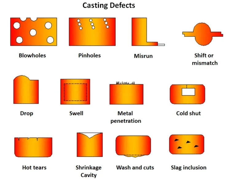
A casting can pass every dimensional check on a CMM and still fail in service. Porosity, shrinkage voids, and inclusions form during solidification, buried inside the metal where callipers and even surface scanning never reach them. The part looks right, measures right on the outside, and then cracks under load three weeks after it’s shipped because a void sat exactly where the load path ran through it.
Sectioning used to be the only way to check. Cut the part open, polish the section, look under a microscope, and hope the defect you’re worried about happened to sit on the plane you cut through. It destroyed the part and only told you about one cross-section. There was no guarantee the worst void in the casting wasn’t half a millimetre away from your cut line. CT scanning replaces that guesswork with a complete internal record of the part, and it doesn’t destroy anything to get it.
How the scan actually finds a void
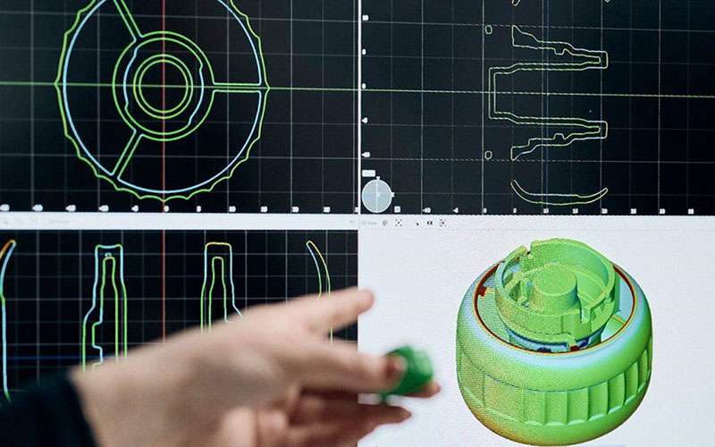
X-rays pass through the casting and lose energy at different rates depending on what they’re travelling through. Solid metal absorbs heavily, a void or gas pocket absorbs almost nothing, and that difference shows up as contrast on the detector. The part rotates through a full 360 degrees while the system captures hundreds or thousands of projections, and reconstruction software compiles those projections into a voxel-based 3D volume, each voxel carrying a density value tied to an exact point inside the part.
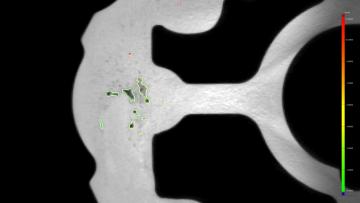
Once that volume exists, porosity analysis software isolates every void above a set size threshold and reports it by location, volume, and shape. A cluster of small round pores near a casting’s core reads very differently to a single elongated void running along a wall, and the software distinguishes between them automatically rather than relying on an inspector eyeballing a single polished section and guessing at what the rest of the part looks like.
Metals behave differently under the beam, and that changes the setup
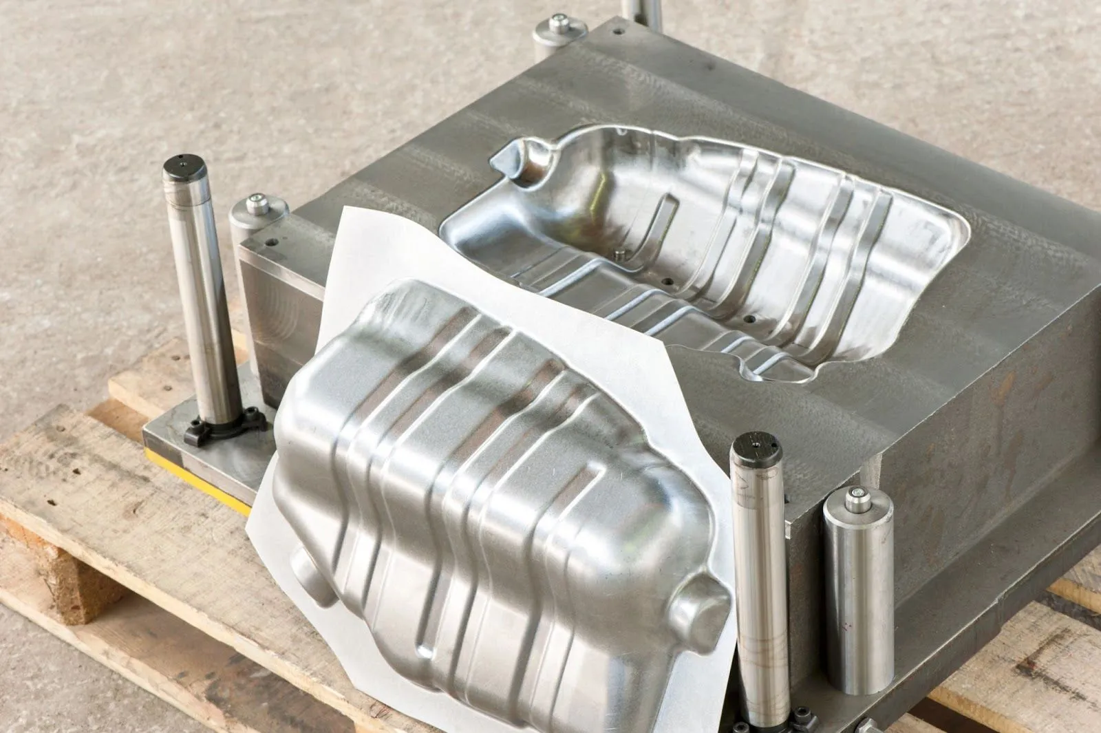
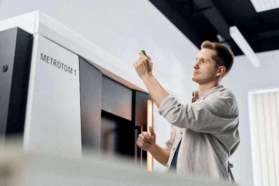
Aluminium castings scan cleanly at relatively low X-ray energy, which keeps scan times short and resolution high. Steel, nickel alloys, and thicker cast sections need considerably higher kV to penetrate the material at all, and pushing power up trades against resolution, so a scan configured for a dense steel housing won’t run at the same voxel resolution you’d get scanning an aluminium bracket of similar size. This is where equipment specification actually matters rather than being a marketing footnote. A system like the ZEISS METROTOM 800 running at 320 kV with a microfocus tube rated up to 500 W handles dense metal sections that a lower-power system simply can’t penetrate cleanly, and running the wrong system against a dense casting produces noisy, unreliable data rather than a usable result.
Wall thickness variation adds another layer of difficulty. Thin sections next to thick bosses on the same casting need the scan parameters balanced so the thin walls don’t overexpose while the thick sections still penetrate properly. Get that balance wrong and you either lose detail in the thin areas or leave the thick areas under-penetrated and effectively invisible in the reconstructed data.
Sand, die, and investment casting each fail differently
The casting method a part came off changes what you’re actually hunting for inside it. Sand casting tolerates more process variance than the other two methods, which means dimensional drift and porosity both need closer watching, especially on safety-critical parts where a wider tolerance band was never an option to begin with. Die casting runs the opposite problem, high-speed injection traps air in the melt more readily, so gas porosity and cold shuts near thin sections turn up more often than in a slower-filled mould. Investment casting produces the tightest as-cast geometry of the three, but that precision raises the stakes on surface and near-surface defects, since a part sold on dimensional accuracy can’t also carry a void sitting just under a critical surface.
Knowing which failure mode belongs to which process changes how a scan gets set up. A die-cast part gets checked hardest for gas porosity clustered near gate locations and thin ribs. A sand-cast part gets checked across a wider volume for shrinkage porosity that can show up almost anywhere in a thick section as it cools. Treating every casting the same way at the scanning stage wastes resolution on defects that were never likely to occur there in the first place.
Reading the result against a spec, not just a picture
A colour-coded void map looks convincing on a screen, but the number that actually matters to an aerospace or automotive customer is porosity percentage against an agreed acceptance criterion, usually a customer-specific internal spec built around casting soundness. The scan needs to output a defensible number, not just an image, because an auditor asking for objective evidence of casting integrity wants a percentage and a location, not a screenshot.
Nominal-actual comparison against the original CAD model adds a second layer beyond porosity alone. Shrinkage during solidification can pull wall dimensions inward in ways that never show up on an external CMM check if the shrinkage happened around an internal core rather than an external surface. CT scanning catches both problems in the same pass, the internal voids and the dimensional deviation, without needing two separate inspection methods run back to back.
Non-destructive testing that still lets you ship the part
The part being scanned doesn’t have to be a sacrificial sample. Because CT scanning causes no physical damage, first article inspection on a new casting tool can be run on the same part that eventually ships, rather than burning a production unit purely to section it and confirm the tool is producing sound castings. That matters most in low-volume runs where every casting off a new tool carries real cost, and destroying one just to check internal quality eats into a margin that was already tight.
Get the casting scanned before it becomes a warranty claim
If a casting’s been failing intermittently and nobody can explain why, or a new tool needs its first parts checked before the full run commits, bring it to Global TechSolutions. As the ZEISS Partner Metrology Centre in Singapore, we run CT scans on METROTOM systems built to handle everything from thin aluminium brackets to dense steel housings, with results delivered within three working days. Book a scan and find out what’s actually inside the part before your customer does.
Contact Us for a Free Demo
Whether you need a live demo with your own parts or expert measurement services, our specialists are ready to support your quality assurance needs.