



The part with no drawing behind it
Somewhere on your production floor is a component with no drawing behind it. Maybe it came off a machine built in the 1990s, maybe the original supplier folded years ago, maybe it’s a competitor’s part you’ve been asked to match without infringing on anything protected. Whatever got you here, you now need a usable CAD file from a physical object, and guessing dimensions off a set of callipers isn’t going to hold up once that part goes back into a moving assembly.
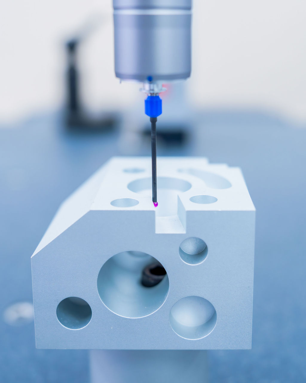
Reverse engineering in a metrology context isn’t sketching. It’s capturing the actual geometry of a physical part through CMM probing, structured light or blue light 3D scanning, or CT scanning when the geometry you need sits inside the part rather than on its surface, then rebuilding that data into a CAD model you can actually machine from, mould from, or hand to an engineer for redesign.
Which capture method actually fits your part
A CMM gives you point data. Fast, accurate to fractions of a micron on the right machine, and the obvious choice for a part with clean geometric features, flat faces, bores, defined edges. What it won’t give you is a full surface mesh of something organic or freeform, a turbine blade profile or a cast housing with compound curves, because point probing simply can’t capture enough of the surface fast enough to be practical.
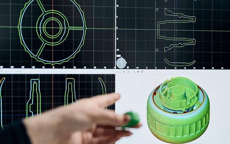
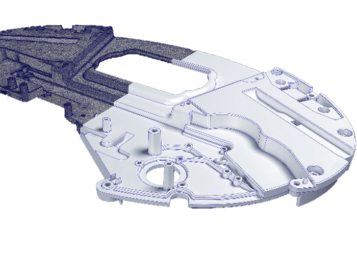
That’s where structured light or blue light scanning takes over. Full-field capture across the whole surface in one pass, producing a point cloud dense enough to reconstruct freeform geometry that a CMM would take hours to approximate badly. The trade-off runs the other way though, surface scanning gives you the outside of the part and nothing about what’s happening underneath it.
If the feature you actually need sits internal to the part, a wall thickness that varies, an internal channel, a cavity geometry from an old casting with no drawing left anywhere, CT scanning is the only method that captures both internal and external geometry in a single non-destructive pass. You get a complete digital record of the component without cutting it open, which matters when the part in front of you is the only surviving sample.
What the actual workflow looks like once the part is on the machine
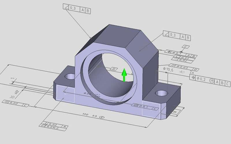
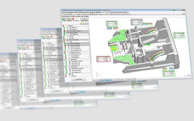
Capture is the easy half. Once the point cloud or mesh exists, someone has to turn it into usable CAD, and this is where a lot of reverse engineering projects go wrong when handled by a scanning shop with no engineering background behind it. Raw mesh data isn’t a CAD model. It needs surface fitting, feature recognition, and a decision on tolerance intent that the original designer never wrote down anywhere, because there’s no drawing to read it off. Get that step wrong and you end up with a model that matches the scanned part exactly, including every manufacturing defect and wear pattern that part picked up over years of service, none of which belongs in a new production drawing.
A properly built reverse engineering deliverable separates what the part actually measured from what the design intent should have been. That means recognising a bore that scanned at 24.97mm was almost certainly meant to be a 25mm nominal with normal tolerance, not modelling it as 24.97mm because that’s what the scanner returned. This is engineering judgement layered on top of measurement data, and it’s the difference between a CAD file you can hand to a machinist with confidence and one that quietly bakes in every flaw of a worn sample part.
Where this gets used in practice
Legacy part replacement is the most common driver. A machine builder goes out of business, the spare part stops being available, and the only way to keep a production line running is to reverse engineer the worn original into a manufacturable file. Tooling and mould repair work the same way, capturing the as-built geometry of a die that’s been hand-finished away from its original drawing over years of use, so a replacement or repair actually matches what the tool has become rather than what it was on day one.
Competitive benchmarking is another driver, and it needs to be handled carefully. Measuring a competitor’s part to understand its geometry is standard practice across manufacturing. Reproducing that geometry in a way that copies protected design elements is a different conversation entirely, and worth a word with your own legal counsel before any file goes into production, not after.
What to check before you commit a part to the process
Ask what capture method the provider defaults to, because a shop that only owns a CMM will try to sell you CMM-based reverse engineering even when your part genuinely needs a scanner or a CT system instead. Ask who does the CAD reconstruction and what their engineering background actually is, since anyone can export a mesh but turning that mesh into design-intent geometry takes real judgement.
Bring the part in, skip the guesswork
Callipers and a hunch won’t survive a design review. If you’ve got a legacy part, a worn tool, or a component you need matched without a single drawing to work from, get in touch with Global TechSolutions and we’ll walk you through which capture method actually fits it.
Contact Us for a Free Demo
Whether you need a live demo with your own parts or expert measurement services, our specialists are ready to support your quality assurance needs.